Hydraulic control valves in tractor
صمامات التحكم فى الجهاز الهيدروليكى فى الجرا ر
1. Load check valve
2. Lift cylinder relief valve
3. Lowering metering valve
4. Lowering solenoid
5. Raise solenoid
6. Raise spool
7. Flow compensating valve

Neutral
• Solenoids not energised
• Oil flow from the parallel gallery A
flows past the flow compensator spool into gallery B where it is blocked by the
lands of the raising spool.
•Oil under the pressure in the hydraulic
lift circuit is prevented from entering gallery E by the load check valve (4)
•The trapped pressurised
oil in the lift circuit is applied to the right hand end of the metering valve
through the small drilling X
•The applied pressure holds the metering
valve in the closed position preventing oil flow from gallery E to the return
to reservoir gallery F
•When the valve is in neutral , gallery C
& load sensing galleries D are open to reservoir through the centre of
the raising spool & gallery F.
gallery
G is a common return to reservoir gallery running through the centre of
the valve stack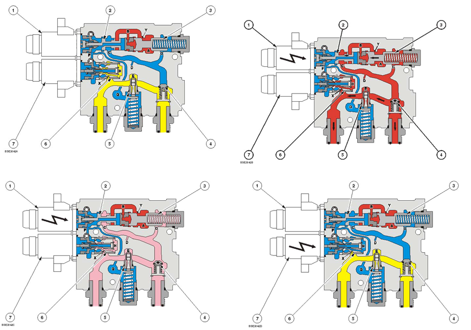
Lowering
• Trapped oil in lift cylinder is vented
through metering valve to reservoir
• Lift drops with gravity and is not
powered down
• Drop rate is electronically controlled
by the processor and solenoid
• 2 stages of valve movement during
lowering

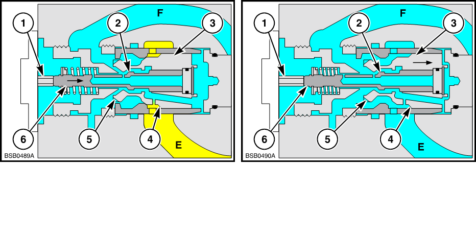
Lowering
( Close up showing operation of
lowering metering valve )
Stage 1
• Lowering solenoid activated
• Plunger ( 1 ) and pilot
spool ( 6 ) moved to right allowing trapped oil at H
to go to reservoir via F past the lands in the pilot spool ( 2 )
• As
oil at H is released, the trapped cylinder oil E acting on the chamfered face (
4 ), will push the metering spool ( 3 )
to the right.
Stage 2
• The
lift cylinder oil can now pass the metering
lands ( 5 ) of the metering spool to reservoir via
F.
• Drop
rate is electronically controlled by the processor and solenoid which adjust
the clearance over the metering
lands ( 4 ).
•


ليست هناك تعليقات:
إرسال تعليق