محول العزم فى محرك الجرار TORQUE
CONVERTER IN TRACTORS

A.
Powershuttle
B.
Powershift

TORQUE
CONVERTER -
The
torque converter is mounted on the flywheel and transmits engine power to the
transmission.
The
unit contains 3 elements:-
1. Turbine - output member
2. Stator with free wheel clutch - Torque multiplication member
3. Pump or impeller - input member

TORQUE
CONVERTER COMPONENTS
A.
Front View
B.
Rear View
C
Exploded View
1. Turbine - output member
2. Stator with free wheel clutch - Torque multiplication member
3. Pump or impeller - input member
4. Front Housing

TORQUE
CONVERTER OPERATING PRINCIPLES -1
A. Torque transmitted by a fluid
The higher the velocity of the fluid, the
greater the torque.
B.
Transmission of torque by air flow between 2 fans.
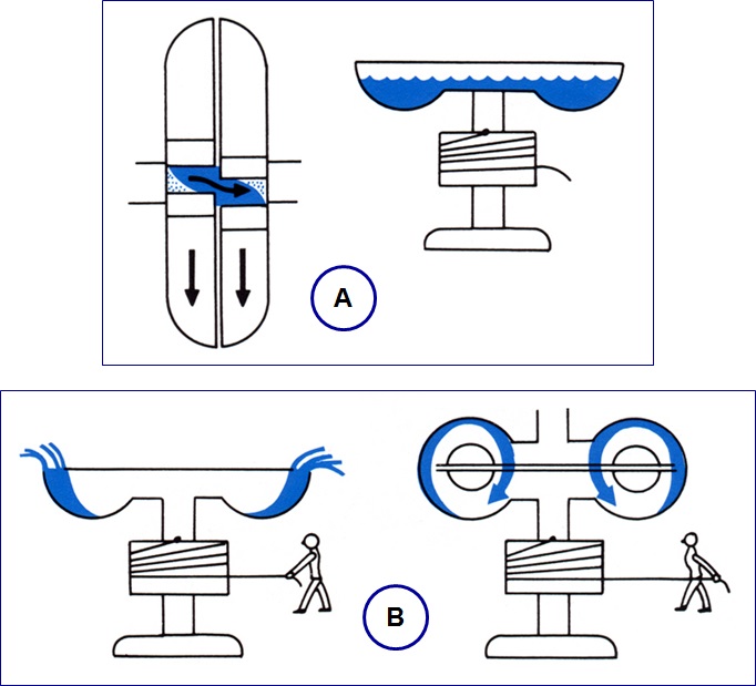
A.
Fluid Coupling consists of two bowls.
The
engine driven one on
the left is called the pump
or impeller.
The output member on the right is called the turbine
Fluid
level lies level with bowl at rest
B.
Fluid Flow when bowl rotates.
Fluid
is thrown out if the bowl spins.
Torque is transmitted to the upper bowl by the
force of the fluid.
This
is a simple Fluid Coupling which will transmit torque as pump speed is
increased, providing an automatic clutch with smooth engagement.

TORQUE
CONVERTER OPERATING PRINCIPLES - 3
1.
Pump or Impeller 2. Stator 3. Turbine
Torque
converter has a third element called the stator.
The
function of the stator is to redirect the oil returning from the turbine to the
pump so it enters the pump vanes in the same direction as pump rotation.
This
enables a torque converter to multiply the engine torque, the increase in
torque is in proportion to the difference in speed between the pump and the
turbine.
Therefore a torque converter is an
automatic clutch which will increase torque in proportion to the load

TORQUE
CONVERTER OPERATING PRINCIPLES - 4
The
stator blades are curved, as C, and their effect is illustrated above by
comparison of fluid spraying onto, A, a flat surface and, B, curved inlet
surface.
The
stator is mounted on a free wheel clutch which locks at low turbine speeds to
provide torque multiplication, but turns when pump and turbine speed become the
same.

TORQUE
CONVERTER OPERATING PRINCIPLES - 5
A.
Vortex Oil Flow
When
the turbine is turning much slower than the pump, lower speed due to the
loading, the internal oil is vortex flow, A, providing torque multiplication.
B.
Vortex & Rotary Oil Flow
As
the turbine speed increases, the oil flow
changes progressively to rotary flow.
C.
Rotary Oil Flow
As
the turbine speed increases to be equal to the pump speed, the oil flow changes
rotary flow.
Torque
is transmitted but not multiplied.

TORQUE
CONVERTER OPERATING PRINCIPLES - 6
P.
Pump S. Stator -
locked T. Turbine
Directional
oil flow from the turbine the turbine to the pump and return through the
stator.
The
turbine blades are designed to match engine power available.

STATOR
OIL FLOWS
Oil
flow returning from turbine to pump is redirected by the stator vanes to return
to the impeller in the same direction as
rotation.
* At
maximum torque multiplication, that is torque converter
(turbine)
stall, return oil flow strikes the stator vanes at point A.
* As
turbine speed increases and multiplication decreases, the return oil flow
strikes the stator vanes progressively further inwards, B to C.
* The
stator is locked by the freewheel clutch
* As
turbine speed approaches impeller speed the return oil flow strikes the back of
the stator vanes, the freewheel clutch allows the stator to rotate with the
impeller and turbine.

STATOR
FREE WHEEL CLUTCH
The
stator clutch remains locked during torque multiplication, conditions A, B & C, when the turbine speed is less than
pump speed.
The
stator clutch allows the stator to freewheel
and turn with the pump & turbine in
condition D,
when turbine speed approaches pump speed.
Torque is transmitted but not multiplied.

TORQUE
CONVERTER PERFORMANCE GRAPH
POWERSHUTLE
TRANSMISSION
Illustrates
relationship between turbine speed and torque multiplication.
Torque
Converter Stall
occurs when the load reduces turbine speed to Zero.
Torque
converter ratio is
the torque multiplication at stall, 2.38:1 means engine torque is multiplied by
2.38.
Hello
ردحذفI visit your blog and read your article. I like the information shared by you. You wrote really very well, I really like your blog and information provided by you. It is very useful information for me and for other peoples also. I hope you will share some more info about Auto Clutch Repair. I appreciate your work. Thanks for sharing such beautiful information.
https://talosdrones.com/
ردحذف